 Send Inquiry
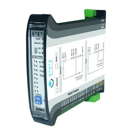
PPI- DOMS-12 Digital Output Module

PPI- DOMS-12 Digital Output Module Specification
- Power Supply
- 24V DC
- Mounting Type
- DIN Rail Mounting
- Size
- Standard
- Frequency
- 50/60 Hz Hertz (HZ)
- Model
- PPI-DOMS-12
- Features
- Compact Design, Reliable Performance, DIN Rail Mountable
- Operating Temperature
- 0 to 60C
- Connectivity Type
- Wired
- Interface Type
- Screw Terminals
- Product Type
- Digital Output Module
- Application
- Communication equipment
- Dimension (L*W*H)
- 115 mm x 100 mm x 22 mm Millimeter (mm)
- Material
- Metal
- Weight
- 120 g Grams (g)
- Protection
- Overload and Short Circuit Protected
- Output Current
- 5A max per channel
- Response Time
- < 10ms
- Output Voltage
- 250V AC / 30V DC max
- Insulation Resistance
- > 100M at 500V DC
- Enclosure Protection
- IP20
- Output Type
- Relay Outputs (NO/NC)
- Indication
- LED for Each Output Channel
PPI- DOMS-12 Digital Output Module Trade Information
- Minimum Order Quantity
- 10 Units
- Payment Terms
- Cash in Advance (CID), Cash Advance (CA), Cash Against Delivery (CAD)
- Supply Ability
- 500 Units Per Month
- Delivery Time
- Days
- Main Domestic Market
- All India
About PPI- DOMS-12 Digital Output Module
- 4 (AOMS-4U) or 8 (AOMS-8U) Analog Output Channels
- Each Channel Independently Programmable for DC Current
(0-20 mA, 4-20 mA & 0-10 mA) or Voltage (0-5 V, 1-5 V & 0-
10 V) Output
- 14 Bit Output Signal Resolution
- Programmable Min / Max Counts Corresponding to Signal
Low & Signal High Outputs
- Programmable Fail-Safe Output Signal Level Against
Communication Link Failure
- Three-way Isolation Eliminates Potential Ground Loops
between Power, Outputs and RS485 Serial Port
- Supports Coils (Bits) & Bit-Mapped Registers MODBUS Data
Type for Most Parameters
2-wire, Half-Duplex, Start-Stop Synchronized RS485 Serial
Port
- Industry Standard MODBUS RTU Protocol with Programmable
ID, Baud Rate & Parity
- Compact DIN-Rail Mount Enclosure : 22.5(W) X 101(H) X
119(D), mm
- Wide Supply Voltage Range : 18 32 VDC (24 VDC Nominal)
- Free PC Tool for Easy Configuration and Parameter SettingsWarranty - Yes
- Feature - Durable
- Condition - New
- Size - Standard
Engineered for Safety and Reliability
The PPI-DOMS-12 is designed to meet rigorous industrial standards, offering overload and short-circuit protection for each output. High insulation resistance ensures safe operation, while the robust metal enclosure with IP20 protection defends against dust and accidental contact. Its DIN rail mountable design allows for secure installation in a variety of control cabinets, supporting dependable performance in communication and automation systems.
Simple Integration and Monitoring
Integration is straightforward thanks to the wired connectivity via screw terminals and LED indication for each output channel. Installers and operators can monitor the de vice status at a glance, benefiting from rapid response times of less than 10ms. The PPI-DOMS-12 fits seamlessly into systems requiring reliable switching of up to 12 digital outputs, powered by a 24V DC supply and supporting frequencies of 50/60Hz.
FAQs of PPI- DOMS-12 Digital Output Module:
Q: How do I install the PPI-DOMS-12 Digital Output Module?
A: The PPI-DOMS-12 features DIN rail mounting, making installation simple in standard industrial control cabinets. Secure the module onto the DIN rail, then connect your wiring to the screw terminals as specified in the manual. Ensure the power supply is 24V DC before powering the unit.Q: What types of loads can the relay outputs control?
A: Each relay output can handle loads up to 5A at 250V AC or 30V DC. The relays are suitable for controlling a wide range of communication equipment, industrial dev ices, lights, motors, or similar components, provided the load does not exceed these limits.Q: When does the LED indication activate on each output channel?
A: Each output channel has a dedicated LED that illuminates when the corresponding relay is engaged, allowing real-time monitoring of the modules operational status without additional testing equipment.Q: Where is the PPI-DOMS-12 commonly used?
A: This digital output module is widely used in communication equipment, industrial automation systems, and control panels, where reliable and secure relay switching is required. Its compact and standard size allows placement in various industrial and commercial settings.Q: What protection features does this module offer?
A: The PPI-DOMS-12 comes with overload and short-circuit protection for each channel, ensuring safe and durable operation even during unexpected faults or power surges.Q: How does the module benefit system integrators and end-users?
A: The PPI-DOMS-12 provides reliable performance, compact design, and straightforward installation. Its quick response time, robust construction, and clear LED indicators reduce setup complexity and maintenance, enhancing overall system efficiency.Q: What is the process for wiring the output connections?
A: To wire the output connections, use the screw terminals for each channel. Reference the modules wiring diagram, and ensure circuits are disconnected from power before making connections, maintaining safety standards throughout the process.Price 5750 INR/ Unit
- Minimum Order Quantity
- 10 Units
- Supply Ability
- 500 Units Per Month
- Delivery Time
- Days
- Main Domestic Market
- All India
 Get Latest Price
Price:
- 50
- 100
- 200
- 250
- 500
- 1000+

More Products in IO Module Category

PPI- CIM Plus-8 Universal Channel Analog Input Module
Minimum Order Quantity : 10 Units
Product Type : Analog Input Module
Material : Metal
Application : Communication equipment
Size : Standard module

PPI- DIMS-16 Digital Input Module
Price 5550 INR / Unit
Minimum Order Quantity : 10 Units
Product Type : Digital Input Module
Material : Metal
Application : Communication equipment
Size : Compact
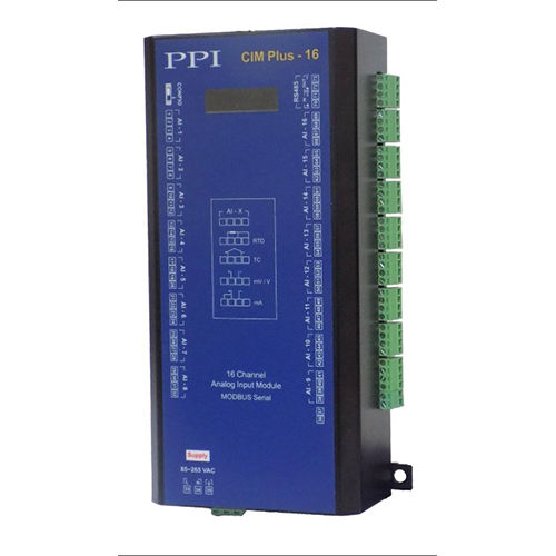
PPI- CIM Plus-16 Universal Channel Analog Input Module
Price 13000 INR / Unit
Minimum Order Quantity : 10 Units
Product Type : PPI CIM Plus16 Universal Channel Analog Input Module
Material : Metal
Application : Communication equipment
Size : Standard
Developed and Managed by Infocom Network Private Limited.

